Draw a boundary wall
This article shows you how to draw a boundary wall object in the Archilogic Editor 4.0
Boundary walls
In some fringe situations, a regular wall is not enough to accurately represent more complex wall arrangements. Here the boundary wall object comes in handy. While a regular wall object is always a rectangular box that stretches from one point to another, the boundary wall object can have an arbitrary shape.
Be advised that a boundary wall object is only meant to be used for small parts of a model that can’t be drawn with regular wall objects. It should not be used to draw all walls of a model as the object type comes with some drawbacks of its own.
For example: You can’t add door or window objects to a boundary wall object, it is currently not possible to assign different materials to different side faces of a boundary wall, and finally, boundary walls provide less accurate relationship information between the nodes of different objects.
Draw a boundary wall
To draw a boundary wall you first have to unlock structural editing.
Once you have unlocked structural editing open the dropdown menu and select the drawing tool for the boundary wall.
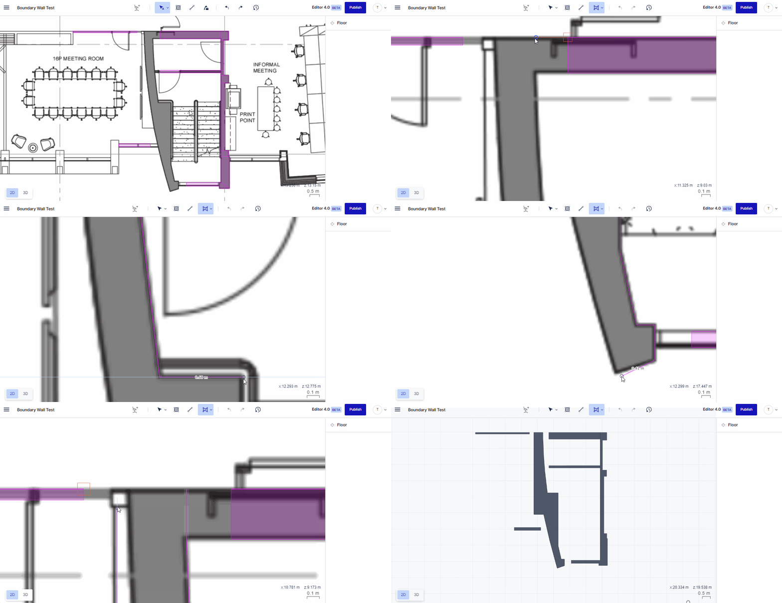
With the drawing tool for boundary walls selected left-click the editor canvas. This will place the first vertex of the object. Move the mouse cursor to the position of another corner and left-click again to place an additional vertex point. Repeat the process until you drew all vertices.
In the end, move the mouse cursor back to the first vertex and left-click it to close the loop and create the boundary wall object.

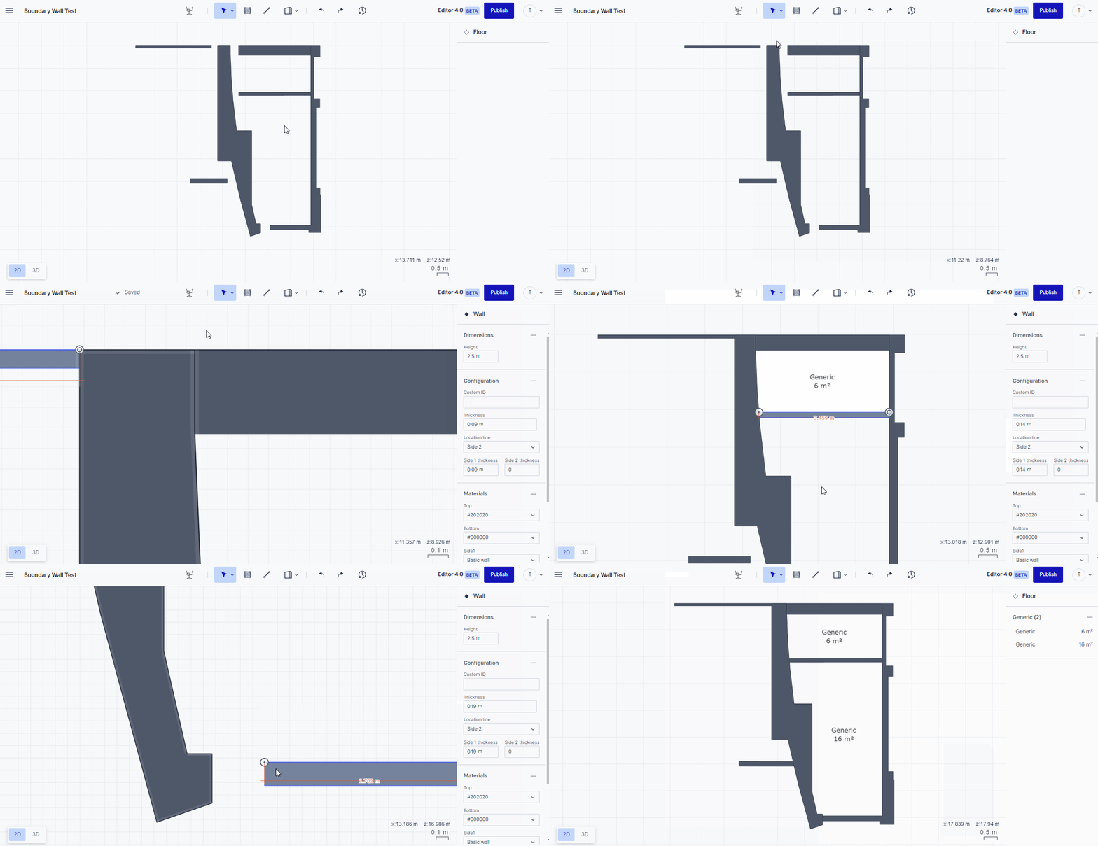
Connect regular walls to a boundary wall
If regular walls and boundary walls are connected on a floor plan it is recommended to always draw the boundary wall first and then connect the regular walls to it instead of drawing the boundary wall already attached to regular walls as this is easier to handle and less prone to introduce mistakes.

