A wall is a structural element used to divide or enclose, and, in building construction, to form the periphery of a room or a building.
In an Archilogic model, spaces are bound by walls and/or space dividers.
To draw or configure a wall in the editor, you must first unlock structural editing mode.
Drawing a wall
To draw a new wall, open the drawing drop-down menu by left-clicking the drawing icon in the menu bar on the top and selecting the wall drawing tool. The selected drawing tool will replace the icon of the drawing menu. You can see if the drawing tool is active if it has a blue background.
You can also type the keyboard shortcut WA on Mac or Windows to activate the wall tool.
With the wall tool activated, move the mouse cursor to the canvas, left-click where you want to start drawing a wall, move your mouse cursor, and then left-click again where you want the wall to end.
Snap the end of the wall that you’re currently drawing to an already existing wall to end the wall drawing action. You can then continue drawing a new unconnected wall somewhere else by left-clicking into the canvas again.
If you don’t snap the end of the wall that you’re currently drawing to an already existing wall, you will stay in the drawing mode after left-clicking a second time, and you can continue drawing connected wall segments until you either snap to an already existing wall or close a wall loop.
Double-click the left mouse button or press the Enter key on your keyboard to place the walls you’ve drawn without closing a loop or snapping to another wall
At any given time, you can exit the wall drawing mode and cancel all unconfirmed walls by pressing the Esc key on your keyboard.
Learn more about how to split a wall in two and add windows or doors.
Creating a space with connected walls
You can create an enclosed space by connecting the walls. This space is auto-generated with a floor and a ceiling, which you can then further configure. Once you’ve created a space, you can assign a usage to it. To align the last wall with the first drawn wall, simply move the mouse cursor to the beginning of the first wall to get a snapping target, then continue drawing with this snapping target and close the wall loop.

Changing the location line of a wall
While in the wall drawing mode, you can press the space bar to toggle through the different location line settings. You can toggle through Side 1, Center, and Side 2. If “Side 1” is selected, the wall width extends towards “Side 2” and vice versa. If “Center” is selected, the location line will be in the middle of the wall, with the wall width extending symmetrically in both directions.
This also works for already-drawn walls. Simply select a wall by left-clicking it and then press the space bar to toggle through the different location line settings.
Alternatively, you can also change the location line of a selected wall through the inspector panel.
Changing the wall width
While in the wall drawing mode or after selecting a wall segment, you can use the N and M keys on your keyboard to change the wall width. N reduces the wall width while M increases it.
The wall width will always increase towards the opposite side currently selected as a location line. If the setting “center” is selected for the location line, then the width will extend towards both sides of the wall.
Wall Properties
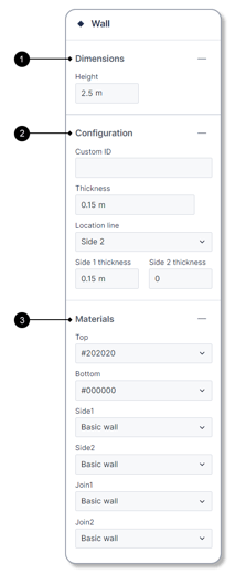
1. Dimensions
The height value controls the wall height.
2. Configuration
The CustomID field allows you to add a custom value with which you can identify the wall segment.
The Thickness value shows the overall wall thickness. It consists of the side 1 and side 2 thicknesses.
The Location line value determines where the location line of the wall segment is located. It can either be on side 1, the center of the wall, or on side 2. This value is important when it comes to drawing walls. If the Side 1 and 2 fields both contain numbers larger than 0 and that are not equal, then the location line will be stated as custom.
The Side 1 and Side 2 thickness values control the wall thicknesses of each side of the wall starting from the location line.
3. Materials
The Materials section of the inspector panel allows you to adjust the materials or colors of each side of the wall (Top, Bottom, Side1, Side2, Join1, Join2). By opening the dropdown menu, you can select from a list of preexisting materials. At the bottom of the dropdown menu, you can also select a simple color value instead.